
Question 21
A conveyor belt system is used to transport packages from a factory to a loading bay, as shown.
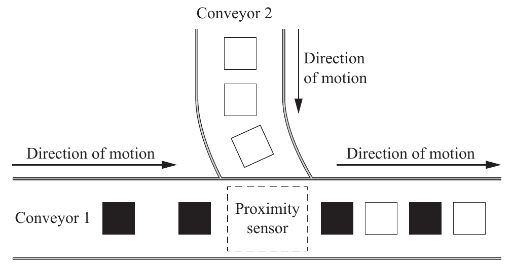
The conveyor belt system has two conveyors. Conveyor 1 has priority and moves continuously when the conveyor belt system is turned on. Conveyor 2 automatically pauses when the proximity sensor detects a package already travelling on conveyor 1. The conveyor belt system has its own power switch, and the factory also has a main power board to turn off all machines at the end of the day. For the conveyor belt system to operate, both the conveyor belt system and the main power board must be turned on. The conveyor belt system stops when the emergency stop button is activated.
Construct a logic gate circuit for conveyor 2, clearly labelling all inputs and outputs. Complete the corresponding truth table on the next page.
Key
Input A = Main power board (on = 1)
Input B = Conveyor belt system (on = 1)
Input C = Proximity sensor (package detected = 1)
Input D = Emergency stop button (activated = 1)
E and F are intermediate input/output signals to the logic gates.
Output X = Power to conveyor 2 (belt on = 1)
| Inputs | Intermediate signals | Output | ||||
|---|---|---|---|---|---|---|
| A | B | C | D | E | F | X |
| 0 | 0 | 0 | 0 | 1 | ||
| 0 | 0 | 0 | 1 | 0 | ||
| 0 | 0 | 1 | 0 | 0 | ||
| 0 | 0 | 1 | 1 | 0 | ||
| 0 | 1 | 0 | 0 | 1 | ||
| 0 | 1 | 0 | 1 | 0 | ||
| 0 | 1 | 1 | 0 | 0 | ||
| 0 | 1 | 1 | 1 | 0 | ||
| 1 | 0 | 0 | 0 | 1 | ||
| 1 | 0 | 0 | 1 | 0 | ||
| 1 | 0 | 1 | 0 | 0 | ||
| 1 | 0 | 1 | 1 | 0 | ||
| 1 | 1 | 0 | 0 | 1 | ||
| 1 | 1 | 0 | 1 | 0 | ||
| 1 | 1 | 1 | 0 | 0 | ||
| 1 | 1 | 1 | 1 | 0 | ||
Conveyor 2 runs only when both power inputs are on and both stop signals are clear
Watch a package on conveyor 1 reach the sensor, then the emergency stop go down. The seven signals underneath follow the key.
Two things must be true for conveyor 2. Both power inputs are on (an AND), and neither the sensor nor the emergency stop is active (a NOR). A final AND joins them.
Build either method, then complete the truth table
Pick a gate for each slot and add the labels. Then fill columns E and X yourself by pressing the cells, or let your circuit fill them row by row. The marking guide ticks off each criterion you earn.
Press an E or X cell to cycle it through blank, 0 and 1. Press A B C D to set the circuit’s inputs. F is printed on the paper.
Column X is marked against your own column E. The guide says “Allow FT mark for column X based on values for column E.”
Work through the solution one mark at a time
Try each step yourself before you reveal it.
Start from the output and ask what must be true for conveyor 2 to get power. First, “both the conveyor belt system and the main power board must be turned on”. Both inputs at 1 is an AND gate, AND1, and its output is E.
Ignore the sentence about conveyor 1 having priority. It describes conveyor 1, and the circuit is for conveyor 2.
Marker: provides a correctly applied logic gate circuit, including main power board and conveyor belt system → AND1 → AND2 → conveyor 2
Second, conveyor 2 “pauses” when the sensor detects a package and the system “stops” when the emergency stop is activated. So C and D must both be 0 for the belt to run. A gate that gives 1 only when both inputs are 0 is a NOR. Its output is F, and the printed F column is exactly the NOR table: 1 in the four rows where C = 0 and D = 0. A final AND gate, AND2, joins E and F to power conveyor 2.
Method 2 in the guide inverts each input instead. NOT1 on the sensor and NOT2 on the emergency stop feed AND2, which gives F, and AND3 joins E and F. The two methods agree on every row (De Morgan’s law) and both earn full marks.
Marker: proximity sensor → NOR → AND2 → conveyor 2 · emergency stop button → NOR → AND2 → conveyor 2. Method 2: proximity sensor → NOT1 → AND2 → AND3 → conveyor 2 · emergency stop button → NOT2 → AND2 → AND3 → conveyor 2
Label the two power inputs, the sensor, the emergency stop and the output. Give each its letter, its name and what 1 means for it.
This guide accepted the letters A to X on their own, because the paper printed a key. Write the names and the 1 conditions anyway. The 2022 guide only awarded label marks when the yes and no conditions were included, and you will not know which rule applies on the day.
Marker: correctly labels main power board input and conveyor belt system input · proximity sensor input · emergency stop button input · power to conveyor 2 output. “Accept inputs/outputs labelled as letters A–X without the component names, e.g. main power board.”
Column E is the output of AND1, so it is 1 only where A = 1 and B = 1. That is the last four rows. The other twelve are 0.
Marker: correctly completes column E
Column X is E AND F. Only one row has both equal to 1, the row A B C D = 1 1 0 0. A safety interlock should let very few rows through, so one row is the check that the whole answer hangs together.
| A | B | C | D | E | F | X |
|---|---|---|---|---|---|---|
| 0 | 0 | 0 | 0 | 0 | 1 | 0 |
| 0 | 0 | 0 | 1 | 0 | 0 | 0 |
| 0 | 0 | 1 | 0 | 0 | 0 | 0 |
| 0 | 0 | 1 | 1 | 0 | 0 | 0 |
| 0 | 1 | 0 | 0 | 0 | 1 | 0 |
| 0 | 1 | 0 | 1 | 0 | 0 | 0 |
| 0 | 1 | 1 | 0 | 0 | 0 | 0 |
| 0 | 1 | 1 | 1 | 0 | 0 | 0 |
| 1 | 0 | 0 | 0 | 0 | 1 | 0 |
| 1 | 0 | 0 | 1 | 0 | 0 | 0 |
| 1 | 0 | 1 | 0 | 0 | 0 | 0 |
| 1 | 0 | 1 | 1 | 0 | 0 | 0 |
| 1 | 1 | 0 | 0 | 1 | 1 | 1 |
| 1 | 1 | 0 | 1 | 1 | 0 | 0 |
| 1 | 1 | 1 | 0 | 1 | 0 | 0 |
| 1 | 1 | 1 | 1 | 1 | 0 | 0 |
This mark follows through from your column E. A wrong E with an X that correctly combines it with F still earns this mark.
Marker: completes column X. “Allow FT mark for column X based on values for column E.”
Each phrase of the question gave you something
The 2025 subject report used Question 21 to show a high-level response, with a correctly applied circuit, every input and output clearly labelled, and columns E and X correctly completed. Its advice to teachers asks for practice at turning specific conditions into circuits with clearly annotated inputs and outputs, including their on and off conditions, in unfamiliar contexts.
QCAA did not publish a band for this question. It reads as complex unfamiliar because you build the circuit from a paragraph that mixes the conveyor 2 rules with a sentence about conveyor 1, and the key condition is an inversion of two inputs at once, the NOR. It was also the first logic question placed in Section 3.
If I had to guess where you might lose marks, it would be the sensor and the emergency stop. “Pauses when the sensor detects a package” means a 1 on C has to switch the belt off, and wiring C or D straight into an AND does the opposite. Read the printed F column before you draw. It is 1 only when C = 0 and D = 0, which is the NOR handed to you.
Only mark this done when you could do it without help. Reading the solution does not count.
Question wording, any figures and marking-guide steps are from the 2025 QCAA Engineering external assessment, © State of Queensland (QCAA) 2025, licensed under CC BY 4.0, and have been adapted, except where a third-party source is named. Tangent Tuition is not affiliated with the QCAA.
Spot a mistake on this page? Report it